Informação básica
| Modelo Nº. | Máquina Formadora de Tanque Transformador |
| Escopo de produção | Linha de produto |
| Espessura da chapa de aço | 0,5-1,75 mm |
| Comprimento da folha formada | >=290mm |
| Altura da ondulação | 50-400mm |
| passo de ondulação | >=40mm |
| Precisão do passo de ondulação | ±0,25mm |
| Intervalo interno de ondulação | 6mm |
| Pressão Máxima | 25MPa |
| fluxo máximo | 200L/Min |
| Pressão hidráulica | 16MPa |
| Diâmetro interno da bobina | Mín. 470 mm, Máx. 520 mm |
| Pacote de transporte | Cabo de aço. |
| Especificação | 300-1300mm |
| Marca comercial | NA FONTE |
| Origem | China, Zhejiang |
| Código SH | 85041900 |
| Capacidade de produção | 500 |
Descrição do produto
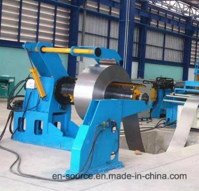
I Layout geral para a linha de produção de aletas de corrugação de transformadores (formação de aletas, soldagem de emendas e bordas de aletas, soldagem de varetas de reforço, soldagem a ponto, dobra vertical e montagem de tanques)
Construção da linha de produção de aletas onduladas do transformador conforme os desenhos mostrados1. Unidade formadora de aletas onduladas do transformador1 Máquina automática hidráulica do desbobinador 2 Máquina formadora de aletas onduladas do transformador automático3 Máquina hidráulica de cisalhamento e embainhamento de placas4 Sistema hidráulico5 Sistema de controle elétrico2. Unidade de soldagem de aletas onduladas do transformador6 Transportador de rolos7 Máquina de solda automática de aletas onduladas3. Transformador ondulado Fin Spot Welding Unit8 Máquina de solda a ponto para Fin Embossment4. Unidade de dobra vertical de aleta ondulada do transformador9 Máquina de dobra vertical hidráulica5. Unidade de montagem de tanque corrugado10 Manipulador de montagem de tanque para tanques corrugadosIntrodução geral da linha de produção de aletas corrugadas para transformadores A linha de produção de aletas onduladas é um equipamento especial para a fabricação de tanques de óleo de transformador selados e isentos de manutenção. Processo de produção principal: desbobinar o material, formar placa corrugada, cisalhar e bainha placa corrugada, transportar e soldar bordas de extremidades corrugadas, haste de reforço de solda, relevo de aleta de solda, dobrar a aleta ondulada acabada, tanque de aço corrugado de montagem. Parâmetros técnicos principais do transformador corrugado Linha de produção de aletas 1. Largura da ondulação: 300~1300mm 2. Espessura da chapa de aço: 0,5-1,75mm 3. Comprimento da chapa formada: >=290mm 4. Altura da ondulação: 50-400mm 5. Passo da ondulação: >=40mm 6. Precisão do passo da ondulação: ±0,25 mm 7. Folga interna da ondulação: 6 mm 8. Máx. Pressão: 25MPa 9. Máx. Fluxo: 200L/min
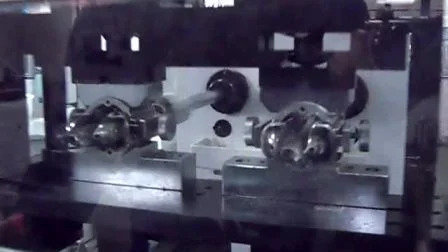
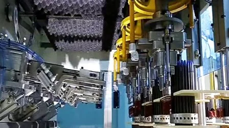
=40mm 4) Plate thickness: 0.5mm-1.75mm 5) Forming speed: 3-4fins/min 6) Power: 28KW 7) Number of pumps: 2 (two separate plunger pumps) 8) Control system: electrical, hydraulic and control board(3) Hydraulic Plate Shearing and Hemming Machine 3.1 Performance Features of Hydraulic Plate Shearing and Hemming Machine This device is used to shear and hem corrugated steel fins. If the fins with this hemming edge, you can make "corrugated fin tank" more easily, and weld different pieces of corrugated fins into a transformer tank more tightly. It consists of lower shearing blade and movable upper shearing blade, which is mounted on a pillar guides. The shear blades are made from tool steel, it can shear over 100 thousand times after each sharpening with the minimum burr. Shearing and hemming of the corrugated steel sheet can be done manually or automatically by feeding mechanism. The shearing and hemming of the corrugated steel sheet is hydraulically driven.3.2 Parameters of Our Hydraulic Plate Shearing and Hemming Machine 1) Shearing width: 300mm-1300mm 2) Corrugation height: <=400mm 3) Shearing thickness: <=2.0mm 4) Shearing time: 3-5seconds/time 5) Hemming function is optional, hemming height: 20mm (Available to be chosen from18mm to 25mm but should be fixed)(4) Hydraulic System The hydraulic system consists of oil tank, pump, motor and regulating valves for oil-ways. The main hydraulic elements are supplied by Rexroth Company, Germany.4.1 Parameters of Our Hydraulic Station 1) Max. Pressure: 25MPa 2) Max. Flux: 200L/min 3) Pump motor power: 28KW4.2 Pictures of Our Hydraulic Station (5) Electrical Control System5.1 Electrical control system consists of main control cabinet, operation console, local operation panel and connection wires etc. All the relays, switches, transformers and PLC are mounted in the main control cabinet. MITSUBISHI controller have been adopted to fulfill the control of the production line. The sheet feeder and welding torch movement are controlled by MITSUBISHI AC Servo drive system. The SCHNEIDER Monitor has been introduced to the line as man-machine interface. The control console is equipped with the SCHNEIDER color touch screen, buttons, and indicating lights. The lamination shapes selection(like fin width, fin height and pitch) and parameters adjustment can be fulfilled easily through the SCHNEIDER color touch screen monitor. Automatic circulatory operation is fulfilled after the related parameters have been input. Local control panels equipped in different parts of the production line can realize manual operation.5.2 Pictures of Our Control System(Control Station, Control Panel (6) Roller Conveyor6.1 Features of Roller Conveyor The transport rollers are used to convey the sheared and hemmed corrugated sheets to the welding device. The roller conveyor is equipped with ball bearing for flexible conveyance without motorization. 6.2 Pictures of Roller Conveyor(7) Corrugated Fin Automatic Welding Machine7.1 Introduction of Our Corrugated Fin Automatic Welding Machine The welding device is used to weld the corrugation ends edges and reinforcing rod with MAG welding mode and the diameter of round rod bar is 6mm~8mm. It consists of corrugated steel sheet conveying mechanism, welding torches elevating mechanism, amplitude modulation mechanism and one machine hand. 1) Corrugated steel sheet conveying mechanism: It can transport the corrugated steel sheet to the right welding position according to welding program. 2) Welding clamps and welding torches elevating mechanism: Each pair of welding clamps is driven by an air cylinder via link drive mechanism to hold and release the workpiece. The welding torches are mounted on slide which is driven by servo motor up and down along rolling guide via ball screw shaft. 3) Amplitude modulation mechanism: Two sets of welding clamps and welding torch moving mechanisms mounted on slide are arranged on both side of the line. Distance between the two slides is adjustable along the rolling guide with a centering lead screw. 4) Machine hand In case of missing seam welding, we use the machine hand to push corrugated fin to the welding position, and this machine hand is driven by air cylinder. Auto welders: Two sets of Panasonic Welders are installed in the line. 7.2 Specifications of the welder are as following: 1) Welding speed: Vs=0.5~1 m/min 2) Welding wire feeding speed: Vd=3.4~6 m/min 3) Electric arc voltage:15-16V 4) Welding current: 50-60A 5) Diameter of welding wire: 0.8 mm 6) Shield gas: 85% Ar+15% CO2 7) Consumption of shield gas: 15 L/min 8) Tip length of welding wire: 7~10 mm(8) Spot Welding Machine for Fin Embossment8.1 General Introduction of Our Spot Welding Machine (i.e. Fin embossments spot welding machine) This spot welding machine is used to increase the strength of reinforcement slots(embossment).8.2 Main Units of Corrugated Fin Spot Welding Machine : 1) Conveyor 2) Centering system 3) Clamps & generators 4) Cooling system 5) Control console with computer8.3 Parameters of Corrugated Fin Spot Welding Machine 1) With 2 spot guns. 2) Total rated power: 50KVA x 2 3) Cooling system 4) HMI control system 5) Suitable fin width: 600mm-1600mm 6) Suitable fin height: >=120mm 7) Air Source: Self provided. 8) Air pressure: 0.6Mpa(minimum) 8.4 Pictures of Corrugated Fin Spot Welding Machine Running Machine Finished Products (9) Hydraulic Vertical Bending Machine 9.1 This hydraulic vertical bending machine allows to form the 4 panels composing the complete transformer tank. Using this system it allows to eliminate 3 weldings, save time of assembling and welding the tank with a reduction of leakage risks. 9.2 Main Units of Hydraulic Vertical Bending Machine: 1) Bending system 2) Safety system for the operator 3) Hydraulic unit 4) Control panel 9.3 Main Parameters of Hydraulic Vertical Bending Machine: 1) Sheet thickness(Max.): 1.75mm 2) Panel width(Max.): 1300mm 3) Panel fin height: 50-400mm 4) Distance between panels(Min.): 60mm 5) Power: 5.5Kw 6) Hydraulic pressure: 10MPa 9.4 Pictures of Hydraulic Vertical Bending Machine: (10) Tank Assembly Manipulator for Corrugated Tanks10.1 Main Features of Tank Assembly Manipulator for Corrugated Tanks Tank assembly manipulator is designed for fast and easy assembly of the top frame, tank bottom and the four corrugated panels to make a complete tank.10.2 Main Units of Tank Assembly Manipulator for Corrugated Tanks: 1) The base frame 2) The hydraulic expanding head 3) A small hydraulic power pack 4) 4 sets clamp arms10.3 Specific Technical Data 1) Basic parameters of equipment: Rated power: 4KW Rated voltage: 380V Rated pressure: 0.8MPa Rated oil pressure: 3MPa 2) Tank inside dimensions: Min (W) 285mm to 900 mm Max (L) 600mm to 1500mm10.4 Pictures of Tank Assembly Manipulator for Corrugated Tanks: 2. Technical Parameters of this Transformer Corrugated Finbr>
|
|
|
|
| =45mm or >=40mm/td> |
|
|
|